Motorcycle Signal Indicator

Goal: To create a motorcycle turn signal indicator that is safely and easily seen by the rider
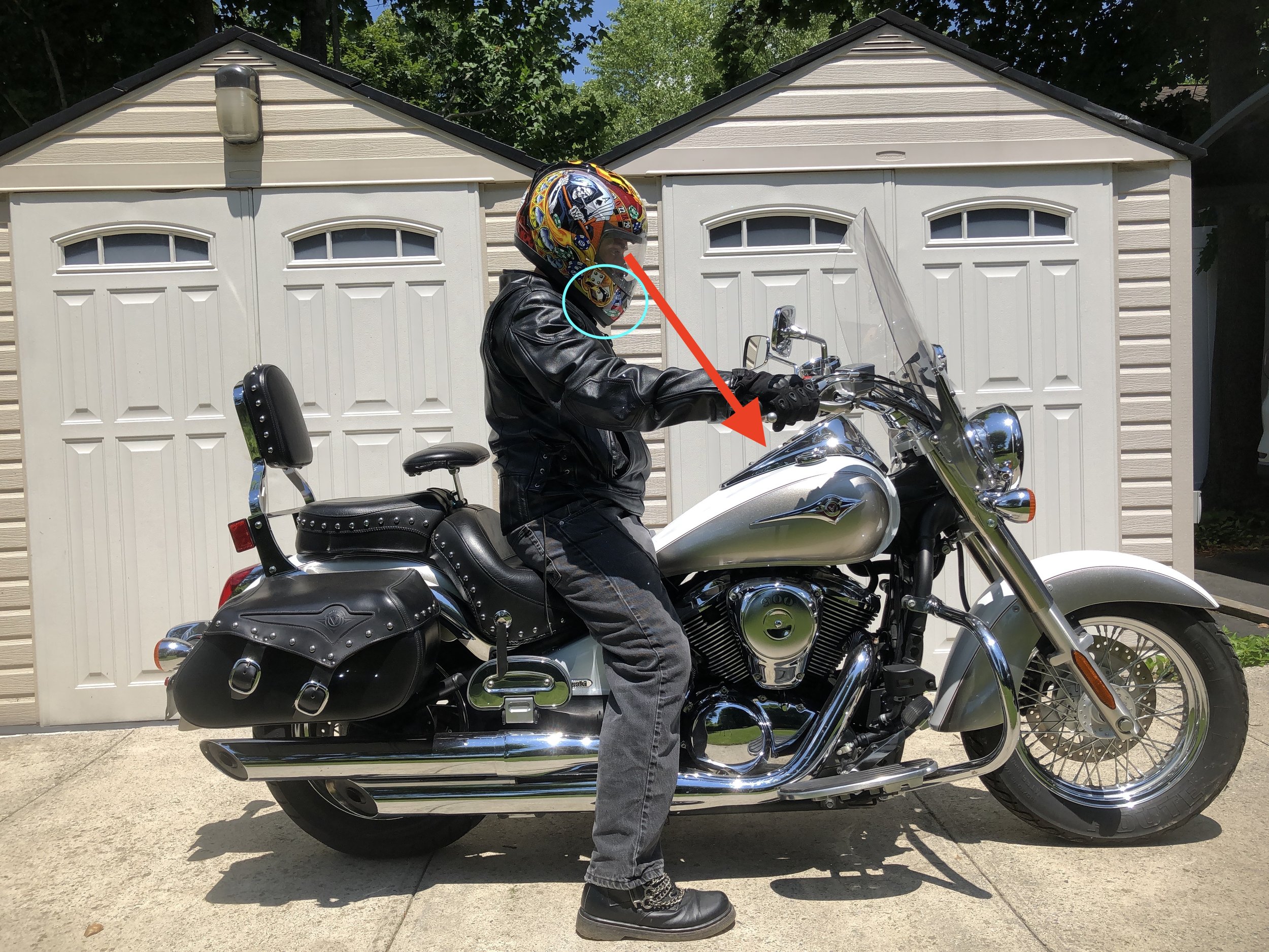
Problem: The stock turn signal indicator on this motorcycle sits close in to the rider and is also at an angle which cannot easily be seen. This causes the rider to take their eyes off the road to check the indicator which leads to unsafe riding conditions. This is amplified by riders wearing a full-face helmet as the chin section of the helmet requires a deeper angle to be able to see the indicator. This motorcycle model also does not have a cancellation timer and the signal only turns off with user input (via handlebar button), so if the rider is not aware that the signal is on, they can ride indefinitely with the turn signal on. This creates an unsafe environment for all vehicle operators as individuals can assume the turn signal is intentional and react accordingly.

After brainstorming, it was determined that a unit could be created which wraps around the handlebar so it can be within the rider’s field of vision, does not hang freely off the bar and can also have a limited footprint.
Version 1 was centered around a standard LED bulb with integrated tracks for the leads of the bulb
After building in Fusion360 and printing, a number of issues were found with version 1:
The walls of the unit were too thin and cracked when the LED was inserted
Trying to get the LED leads into the tracks was very difficult
Would be difficult to replace the bulb if necessary
Not water/weatherproof - though it was considered to add a cap to cover the LED bulb
No secure way to attach to handlebar - could only use double stick tape which may fail
Somewhat bulky design/not aesthetically pleasing


Version 2 was still centered around a handlebar-anchored design; however, the issues of version 1 were considered and addressed when brainstorming for this next iteration:
The width of the unit was greatly increased - this allowed for additional design changes as well as more surface area for double-stick tape to assist with mounting
The larger width allowed for incorporation of 2 tracks running the length of the unit sides to be able to secure the indicators to the handlebars with zip ties
For waterproofing and a more sleek design, a slot was added into the middle of the unit to fit a waterproof SMD. While SMDs also have a long use-life, this allows for easy SMD replacement if needed.
To help with securing the unit to the handlebar, this iteration was based upon a 260 degree arc to incorporate a small wraparound on the bar.
After building version 2 in Fusion360 and printing, this design seemed to be appropriate in meeting the project requirements.
However, when attempting a fitment test before adding the SMDs, it was discovered that the resin material was too rigid and cracked when trying to put it on the handlebar as too much flex was required to push the unit into place.


As the only issue with version 2 was the length of the arc, version 3 retained all of the design elements while adjusting to a basis on a 225 degree arc so there is still some wraparound but less bending/flexing for applying to the handlebar.
This design was successfully applied to the handlebar (and also removed), so test fitting for the SMDs and zip ties was also carried out and successful.
Silicon was also added to the SMD opening to seal the SMDs into the track and for additional waterproofing.
With the units designed and printed, the next item to work out was wiring. The hope here was that the stock bike would have some type of quick disconnect built into the turn signals to run leads from; however, this bike had a full wire running from the turn signals into the pin connector leading to the dashboard.
As such, the wiring diagram was consulted to determine which pins corresponded to the turn signal indicator bulb on the dash. Since one bulb is used for both the left and right signal, this meant both of the indicator units could be wired to the same pins. Before proceeding with hardwiring, loose test wiring was carried out to confirm the correct pins were being used and that the units worked. From this test wiring, it was discovered that the dash indicator light works on an alternating current system, so one side is the positive of one signal and the negative of the other signal while the other side is the opposite.
With this knowledge of how the electronics work, it was decided to solder the leads of the indicator units together to cut down to 2 wires going into the pin connectors instead of 4. Shrinkwrap was also used to help clean up the wires.
Once the wires were properly combined and the pins were properly identified, the wire leads were then soldered to the respective pins and placed back into the pin connector


With the units hardwired in and successfully tested, all that remained was mounting them to the handlebar.
This began with selecting a location and applying double-stick tape to help hold the unit in place.
After snapping the units onto the handlebar and tape, zipties were run through the respective tracks and tightened down to lock the indicators in place.
Some light wire clean up was needed to shorten the leads, leaving enough room to accommodate rotation of the handlebar while not being too long to drag or be a hazard.
After a wipedown with a microfiber towel for cleanup, the units had a successful final function test, completing the project.
As seen in the following image, the new location of the turn signal indicators are much easier and safer for the rider to see during operation, as they remain within the rider’s field of vision without a need to take attention off the road.